Brief Information About Shear Force And Bending Moment Diagrams Engineering Discoveries
Shear force and bending moment diagrams are powerful graphical methods that are used to analyze a beam under loading. This page will walk you through what shear forces and bending moments are, why they are useful, the procedure for drawing the diagrams and some other keys aspects as well. If you're not in the mood for reading, just watch the video!

Cantilever Beam Shear Force & Bending Moment Diagram YouTube
Figure 5: Alternative shear and bending moment diagrams for the cantilevered beam. Figure 6: A distributed load and a free-body section. where x0 is the value of x at which q(x)begins,andξis a dummy length variable that looks backward from x. Hence V (x) is the area under the q(x) diagram up to position x. The moment

Brief Information About Shear Force And Bending Moment Diagrams Engineering Discoveries
bending moment diagram is one which shows variation in bending moment along the length of the beam. Example 1 Draw the shear force and bending moment diagrams for the beam shown below a) determine the reactions at the supports. Taking moments about A (clockwise moments =anti-clockwise moments) 10 x2 = 5RC 5RC=20 RC=20/5 =4kN Resolving vertically
What is Shear Force Diagram and Bending Moment Diagram Civil Engineering Blog
Shear force and bending moment diagrams tell us about the underlying state of stress in the structure. So naturally they're the starting point in any design process.

Solved Draw the shearforce and bendingmoment diagrams for
Shear force and bending moment diagrams are analytical tools used in conjunction with structural analysis to help perform structural design by determining the value of shear forces and bending moments at a given point of a structural element such as a beam.

Brief Information About Shear Force And Bending Moment Diagrams Engineering Discoveries
These reactions can be determined from free-body diagrams of the beam as a whole (if the beam is statically determinate), and must be found before the problem can proceed. For the beam of Figure 4: ∑Fy = 0 = −VR + P ⇒ VR = P ∑ F y = 0 = − V R + P ⇒ V R = P. The shear and bending moment at x x are then. V(x) = VR = P = constant V ( x.

Shear Force and Bending Moment Diagram Calculator
Introduction Figures 1 through 32 provide a series of shear and moment diagrams with accompanying formulas for design of beams under various static loading conditions. Shear and moment diagrams and formulas are excerpted from the Western Woods Use Book, 4th edition, and are provided herein as a courtesy of Western Wood Products Association.

Learn How To Draw Shear Force And Bending Moment Diagrams Engineering Discoveries
Learn to draw shear force and moment diagrams using 2 methods, step by step. We go through breaking a beam into segments, and then we learn about the relatio.
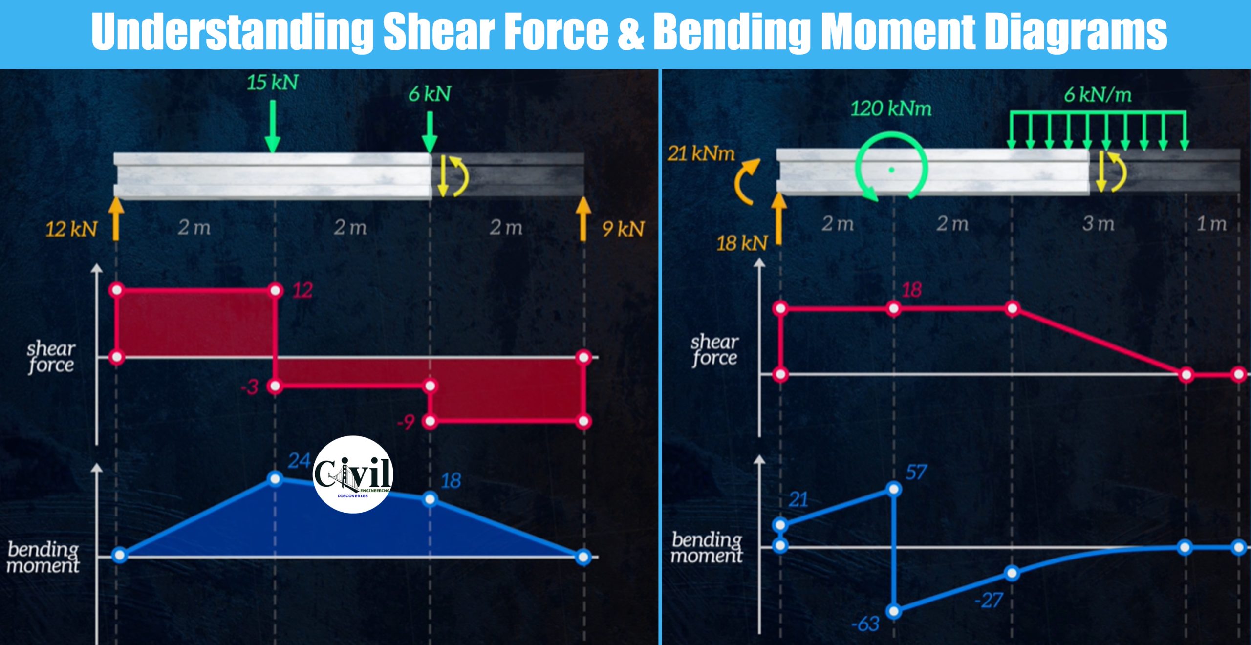
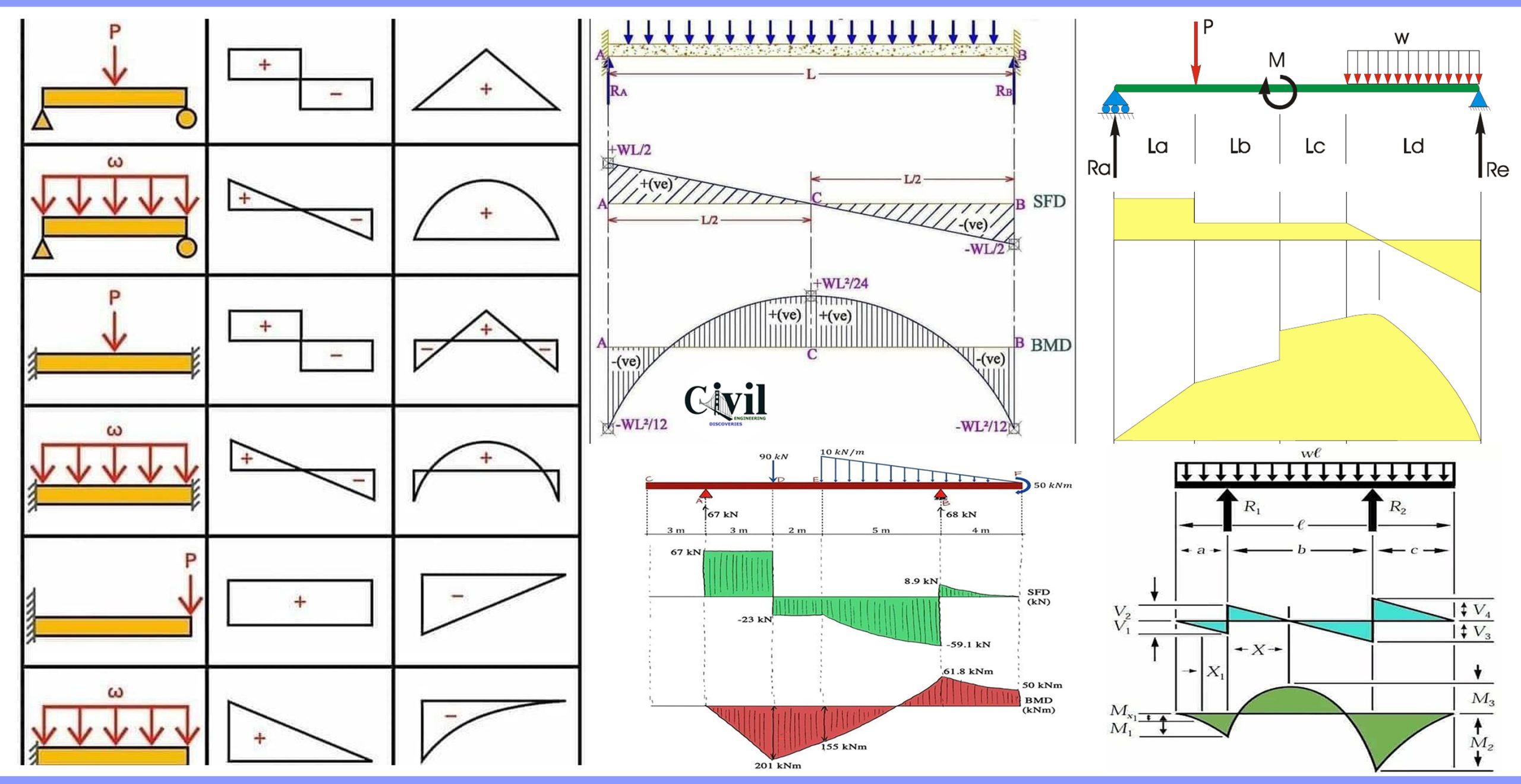
Understanding Shear Force And Bending Moment Diagrams Engineering Discoveries
Shear Force and Bending Moment Diagrams are commonly used to show and analyze the resultant forces in the beam (SFD & BMD). Internal forces are generated within a loaded beam to maintain balance. There are two components to these internal forces: shear forces (directed vertically) and normal forces (oriented along the axis of the beam).

[2015] Statics 27 Shear Force and Bending Moment Functions and Diagrams [with closed caption
INSTRUCTION: Write shear and moment equations for the beams in the following problems. In each problem, let x be the distance measured from left end of the beam. Also, draw shear and moment diagrams, specifying values at all change of loading positions and at points of zero shear. Neglect the mass of the beam in each problem. Tags:

Shear Force and Bending Moment Diagram YouTube
This video explains how to draw shear force diagram and bending moment diagram with easy steps for a simply supported beam loaded with a concentrated load. Shear force diagram.

Ultimate Guide to Shear Force and Bending Moment Diagrams Engineer4Free The 1 Source for
Shear-Force & Bending-Moment Diagrams Graphical Methods Example 1 Given: A simply-supported beam is loaded with a 2 kN-m couple and a 4 kN load as shown. Find: Using graphical methods, draw the shear-force and bending-moment diagrams. dV w(x) , determine an expression for the shear force as a function of
Shear Force and Bending Moment diagram in the horizontal plane. Download Scientific Diagram
Calculate shear force diagrams How to use SkyCiv Beam Calculator Welcome to our Free Beam Calculator! Our calculator generates the Reactions, Shear Force Diagrams (SFD), Bending Moment Diagrams (BMD), deflection, and stress of a cantilever beam or simply supported beam.

Learn How To Draw Shear Force And Bending Moment Diagrams Engineering Discoveries Bending
What are Shear Forces and Bending Moments?.more.more This video is an introduction to shear force and bending moment diagrams.What are Shear Forces and Bending.
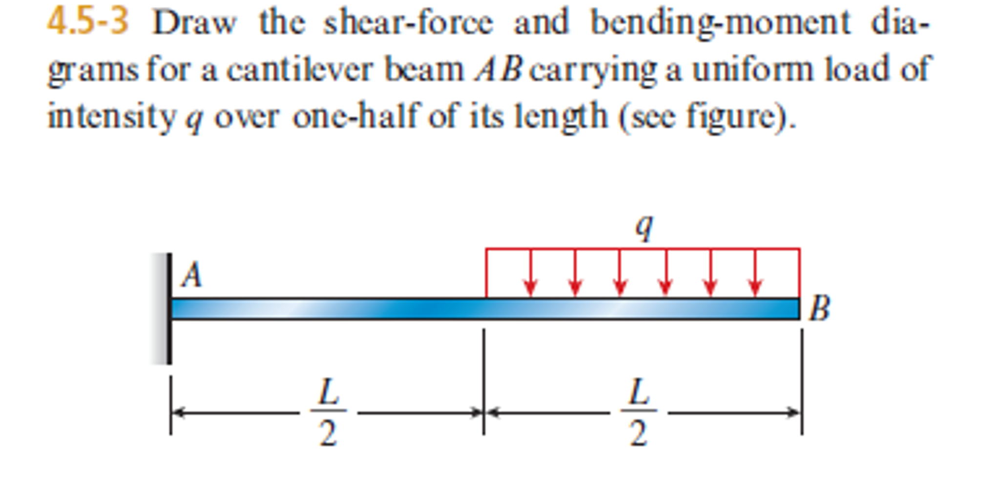
Solved Draw the shearforce and bendingmoment diagrams for
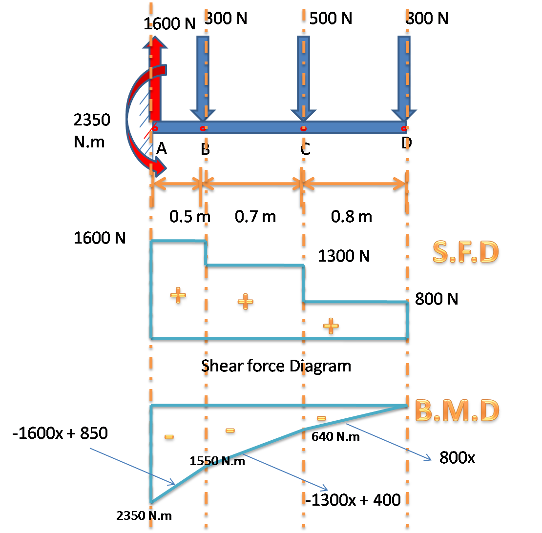
Steps to construct Shear Force and Bending Moment Diagrams. Draw a Free Body Diagram of the beam with global coordinates (x) Calculate the reaction forces using Equilibrium equations ( ∑ forces = 0 and ∑ moments = 0 ) Cut beam to reveal internal forces and moments*. Determine new origin (x n) and use positive sign conventions to label shear.

Shear and moment diagrams indimg
Shear and bending moment diagrams are analytical tools used in conjunction with structural analysis to help perform structural design by determining the value of shear force and bending moment at a given point of a structural element such as a beam. Definition of Shear Force and Bending Moment
